Calumet: First and Forever
Chapter 2: Calumet-Sag Channel and Little Calumet River
Channel Sections 1, 2, and 3, Photos 36–69
(photos 1–35 here)

Photo 2.2.36. November 8, 1917. District electricians are constructing timber power poles along the west side of the canal. The District’s electrical transmission line between Chicago and Lockport ran along the southeast side of the Sanitary & Ship Canal and needed to be diverted at the connection of the Calumet-Sag Channel. (MWRD photo 6271)

Photo 2.2.37. November 19, 1917. Looking southwest along the east side of the Sanitary & Ship Canal, from a point north of where the Calumet-Sag Channel will connect, shows the transmission towers and diversion poles. The diversion is not permanent. The towers and transmission line will be relocated on the southeast side of the canal. (MWRD photo 6290)

Photo 2.2.38. June 24, 1918. Looking southwest, the canal is at right and a small part of the wall has been breached. The connection of the Calumet-Sag Channel to the Sanitary & Ship Canal in section 1 began with excavation of the turning basin behind the canal wall. (MWRD photo 6535)

Photo 2.2.39. June 19, 1918. From across the Sanitary & Ship Canal, looking southeast, the breach in the wall is being backfilled as it was not intended to remove the entire wall before the walls of the new channel were constructed. The limestone masonry canal walls are about 25 years old. (MWRD photo 6513)

Photo 2.2.40. September 23, 1918. Tracks have been laid for a small steam shovel to clear the area for extension of the north channel wall. The track will also be used for the travelling forms for wall construction and concrete deliveries. Both north and south channel walls will be extended to the berm supporting the canal wall before the berm and wall is removed. Puffs of steam in the background are from rock drills. (MWRD photo 6660)

Photo 2.2.41. September 9, 1918. Having reached bedrock, holes have been drilled in the rock and loaded with dynamite to fracture the rock. The broken rock will then be removed to reach the desired bottom elevation. The walls of the Sanitary & Ship Canal appear in the right background and a rock drill is working on the supporting berm. (MWRD photo 6621)

Photo 2.2.42. September 23, 1918. Dynamite blasting too close to the canal wall may lead to premature wall failure. A wide berm is left to support the canal wall while holes are being drilled in the berm. To facilitate later berm and wall removal, dynamite will be placed in the holes. Diversion of the electrical transmission line appears in the background. (MWRD photo 6659)

Photo 2.2.43. September 23, 1918. Double handling of spoil was occasionally necessary as here, south of the channel and east of the turning basin. A large dragline is moving spoil from the right to the left to make space available for more spoil from excavation of the turning basin and removal of the berm supporting the canal wall. (MWRD photo 6661)

Photo 2.2.44. October 14, 1918. District surveyors were important members of the channel construction team. They performed the mapping surveys to design the channel, then, as here, set the horizontal and vertical controls for contractors to construct the channel, ditches, bridges, and roads. (MWRD photo 6679)

Photo 2.2.45. October 14, 1918. The big dragline is removing broken rock from the bottom of the turning basin on, while in the right foreground, surveyor’s assistants are probing the depth to, and soundness of, the bedrock. If the bedrock is sound, wall construction can proceed once the water is pumped out. (MWRD photo 6680)

Photo 2.2.46. November 12, 1918. Turning basin excavation has been completed sufficiently that the south wall foundation can be extended and curved to the southwest. The north wall has also been extended west almost reaching the supporting berm of the Sanitary & Ship Canal wall. (MWRD photo 6720)

Photo 2.2.47. December 16, 1918. In a little over one month, the south wall has been extended and almost completed to the supporting berm in the left foreground. The north wall in the background has also been extend to the supporting berm. The turning basin connected the new channel with the canal. (MWRD photo 6754)

Photo 2.2.48. December 16, 1918. The same scene viewed from the north shows the expanse of the turning basin. As the name implies, the turning basin provided a wide area in the Sanitary & Ship Canal for boats to turn around, but its other purpose was to allow boats to have room to maneuver when turning into the narrow Calumet-Sag Channel. (MWRD photo 6756)
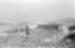
Photo 2.2.49. In two winter months, by February 11, 1919, the lower part of the south turning basin wall has been constructed into the supporting berm. No more wall construction will occur until after the turning basin is flooded and the canal wall and supporting berm is removed. (MWRD photo 6891)

Photo 2.2.50. February 11, 1919. Like the south wall, the lower part of the north turning basin wall has been constructed into the supporting berm. It’s curvature to the north will be completed after the basin is flooded and the supporting berm and canal wall removed. While unremarkable at this moment, this point between the two waterways will become a notable promontory. (MWRD photo 6890)
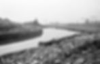
Photo 2.2.51. March 28, 1919. The turning basin has been flooded in preparation of removing the Sanitary & Ship Canal wall and its supporting berm. A few workers on the berm are setting dynamite in the holes that have been drilled along the backside of the canal wall. (MWRD photo 6946)

Photo 2.2.52. March 28, 1919. A group of District trustees and staff members have gathered on, to witness the blasting of the canal wall. It is notable that two women are among the group. At the time, women were not part of the engineering and construction work force. (MWRD photo 6948)

Photo 2.2.53. March 28, 1919. Some blasting of the wall has already occurred. The rock face of the canal wall is missing and most of what remains is the supporting berm. As intended, the blasting was broke up the masonry canal wall and its base. (MWRD photo 6950)

Photo 2.2.54. March 28, 1919. From an overly safe distance, the photographer catches the blast of dynamite sending water into the air. The blast didn’t send rocks into the air because the purpose of the blast was to dislodge and loosen rocks at the bottom of the channel. (MWRD photo 6951)

Photo 2.2.55. March 28, 1919. As water vapor dissipates following the blast, observers head for the end of the north wall to inspect the results and determine if the blasting achieved its intended result. (MWRD photo 6952)

Photo 2.2.56. March 28, 1919. Now that the show is over, some of the dignitaries, in their city clothes typical of the time, prepare to leave. (MWRD photo 6953)

Photo 2.2.57. Following the blast of the canal wall, the bottom of the Sanitary & Ship Canal and of the turning basin had to be cleaned up. Beginning on about April 5, 1919, the big dragline used available spoil to create causeway—called the puddle dam at the time—to support the dragline while it dredged debris off the bottom. (MWRD photo 6968)

Photo 2.2.58. April 5, 1919. The remaining material from the blasting of the canal wall and supporting berm was not sufficiently stable or wide enough to support the dragline. The created puddle dam was wider as the dragline built it and moved north in the turning basin. (MWRD photo 6970)

Photo 2.2.59. April 28, 1919. After more than three weeks, the dragline approached the north end of the turning basin. It was slow and steady work to extend the puddle dam and thoroughly drag the bottom of the canal and turning basin to remove broken rock and sediment. (MWRD photo 7019)

Photo 2.2.60. April 28, 1919. Cleaning the bottom continued to the face of the channel wall at left and the canal wall at right. The dragline and its turntable rests on steel wheels that are supported on an articulated structural steel base with rails. To move forward or backward, sections of the base are lifted and moved from one end to the other end. (MWRD photo 7020)

Photo 2.2.61. The dragline has completed cleaning the bottom and, on May 12, 1919, is in retreat to the south end of the turning basin, removing the puddle dam as it goes. The District’s boat has completed an inspection of the Calumet-Sag Channel and is returning to the Sanitary & Ship Canal. (MWRD photo 7054)
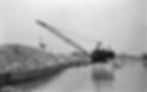
Photo 2.2.62. May 27, 1919. Without the long boom of Heyworth’s large dragline, the job of cleaning the turning basin and canal bottom may have required double handling of material by smaller machines, adding to the cost of construction. (MWRD photo 7083)

Photo 2.2.63. May 27, 1919. Work has begun to construct the wall connecting the existing north wall of the Calumet-Sag Channel with the southeast wall of the Sanitary & Ship Canal, the first step being the building of a timber cofferdam so the connecting wall can be constructed in the dry. (MWRD photo 7085)

Photo 2.2.64. Prior to the availability of interlocking steel sheeting, interlocking timber sheeting, called Wakefield sheeting, was used. On May 27, 1919, the cofferdam sheeting is being set and, when complete, the interior water is pumped out. Leaks are sealed using a diver to apply oakum caulking and clay to the exterior surface of the sheeting. Interior bracing is necessary to resist water pressure in deep cofferdams. (MWRD photo 7084)

Photo 2.2.65. A barge is being used to facilitate construction of the cofferdam and connecting wall. Shown on June 5, 1919, the barge is positioned where the channel opens into the canal. Spoil piles of rock along the channels deterred overland delivery of materials and positioning of equipment for waterfront construction. (MWRD photo 7110)

Photo 2.2.66. June 5, 1919. The small crane on the barge was needed to construct the cofferdam and the wall. Concrete was prepared at a mixing plant located near the railroad bridges half-a-mile east and transported to the construction site by barge. (MWRD photo 7111)

Photo 2.2.67. April 9, 1920, looking northeast with the Sanitary & Ship Canal on the left and the Calumet-Sag Channel on the right: the completed connecting wall. The electrical transmission line has also been restored. (MWRD photo 7485)

Photo 2.2.68. April 15, 1920. From a point southwest of Sag Junction looking northeast, four towers have been reset to the east to include crossing of the Calumet-Sag Channel east of the turning basin. To re-establish the electrical transmission line along the southeast side of the Sanitary & Ship Canal, some realignment was necessary. (MWRD photo 7498)

Photo 2.2.69. June 5, 1919, looking west at the channel cross-section transition in section 3 from vertical concrete or rock walls in the background to trapezoidal armored side slopes with a full depth of water. (MWRD photo 7108)