Draining Chicago
Chapter 4 Photos, 47–69
(photos 1–23 here and 24–46 here)
North Area Sewersheds and Watersheds

Eight square preliminary settling tanks were originally constructed; seven are shown in this October 16, 1927, view. Square tanks were preferred because they were an efficient use of land. Circular settling tanks, however, have proven to be more operationally efficient, thus eight circular preliminary settling tanks were added in 1988, west of the square tanks. Administrative offices and a laboratory were located in the tower. (MWRD photo 13057.1)

June 27, 1928. An empty preliminary settling tank shows the raking mechanism. As the arms slowly rotate, the blades on the bottom move the settled sludge toward the center of the tank where it drops into a sump for removal. Preliminary and final settling tanks operate similarly, but the composition of sludge is different. (MWRD photo 14105)

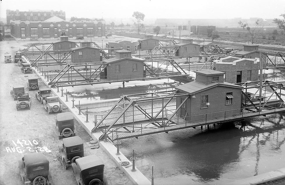
August 2, 1928. The preliminary settling tanks are filled with water and ready for operation in two months. The bridge crossing each tank secures the upper end of the vertical axis for the underwater raking mechanism, and the house on the bridge contains the motor and gear reduction unit for rotating the rake. (MWRD photo 14210)

November 22, 1923. A worker is using a surveyor’s level to set the 60-inch, cast-iron air mains at the proper elevation near the aeration tanks. The connection to the blowers was not made until 1927. Originally, the twin air mains ran underground from the Pump and Blower Building to the aeration tanks. (MWRD photo 10324)

Looking south, June 10, 1924. A five-cubic-yard concrete bucket assists in pouring the floor of the aeration tanks for battery C. A cableway was set up in the north-south direction to deliver equipment and materials for construction of the aeration tanks, operating gallery, and final settling tanks. (MWRD photo 10698)

August 5, 1924. The south end section of two aeration tank sidewalls in battery C have been completed; two ironworkers are preparing the reinforcing rods for the next section of sidewall; and other ironworkers are preparing the south end wall reinforcing rods and wooden forms for concrete placement. (MWRD photo 11034)

The prefabricated steel forms for the 15-foot-high aeration tank walls were reusable. An intermediate wall in battery C, ironworkers are making final connections before concrete will be poured for this section of the wall, July 22, 1924. (MWRD photo 10959)

July 22, 1924. The south cableway tower stands tall above the plant site to the south of battery C, where aeration tank walls are under construction. The tower rides on the two straight tracks to the left. The photographer is elevated on the top of the concrete mixer from which the curved tracks below lead to the cableway tower. To the west of battery C preparations are being made for two more batteries. (MWRD photo 10963.1)

Nearly a year later, on June 18, 1925, battery C is completed and construction is well along for batteries B and A to the west. The operating galleries and final settling tanks are north of the aeration batteries. After the plant was placed in service, the naming of the batteries was reversed with A to C from east to west. Battery D was added to the west in 1962. (MWRD photo 11839.1)

April 14, 1925. A manual gantry crane is used to position materials, piping, baffles, and precast air diffuser plates in the bottom of the aeration tanks. The District experimented with different materials for diffuser plates and manufacturing techniques. The plates used were precast on site in a separate building before installation. (MWRD photo 11669)

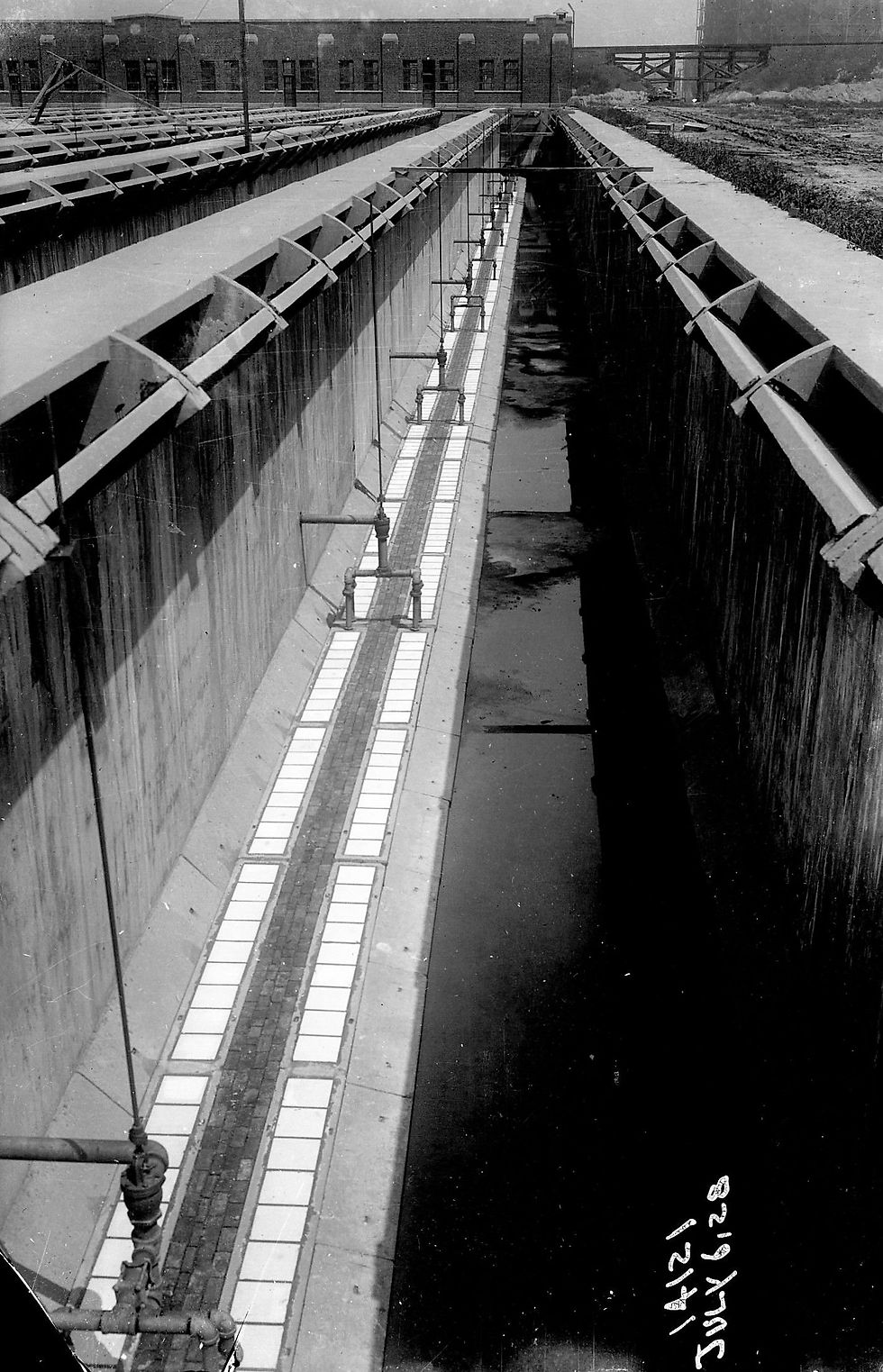
Looking down at interior of an aeration tank, July 6, 1928. Air diffuser plates are in place. Air is piped through the wall to several locations, where connecting pipes protrude as shown and convey the air into the air diffuser plate box through the inverted “U” shaped piping. A valve with an extended vertical stem controls the flow of air. (MWRD photo 14121)

April 15, 2015. Aeration tanks in service. The piping for air delivery to the diffusers has changed, but the process is the same. Further, present technology monitors the dissolved oxygen in the aeration tank and adjusts the flow of air to optimize the process. The aeration tank is the most crucial step in the process of reclaiming water via the activated sludge process. (Photo by author)

Four engineers inspecting the air mains in 1965 died from suffocation due to a lack of oxygen caused by excess methane. As a result, the underground air mains were abandoned and replaced with twin overhead air mains in 1968. One main, shown here on April 15, 2015, continues west to batteries C and D. The other main terminated at batteries A and B. (Photo by author)

The final settling tanks were under the north end of the cableway with walls also constructed with prefabricated steel reusable forms. They were square to make efficient use of the space available. Each lower corner was rounded for efficiency of the rotating raking mechanism, and the floor was sloped to the sump in the center of the tank. (MWRD photo 11141)

July 21, 1925. Laborers are finishing the concrete floor of the final settling tank with the raking mechanism in place for a smooth contact surface. The aerated liquid from the aeration tanks enters the top of the tank along the wall, and the effluent is drawn off by the channels above the raking mechanism. The rake arms rotate slowly and the blades on the rake arm bottom move the settled solids, called sludge, to the center sump for removal from the tank. (MWRD photo 11991)

Looking southwest, June 7, 1928. Final tanks. Originally, ten square final settling tanks were built for each battery. Additional circular final clarifier tanks were added to each battery in 1937 and 1988, the latter to meet more stringent suspended solids effluent limits required by the Clean Water Act. Effluent from the final tanks is piped to the effluent conduit. (MWRD photo 14035)

A typical circular final clarifier tank, April 15, 2015. The aerated liquid from the aeration tanks enters the final tank near the bottom center, then flows vertically and then horizontally toward the effluent trough on the tank perimeter. In the radial flow pattern, the velocity diminishes, facilitating solids settlement. The circular tank design is more efficient than square tank design. (Photo by author)

Laborers are pouring concrete into the wood forms for the crown of the effluent conduit north of the final settling tanks, December 11, 1923. The effluent conduit ran the length along the north side of the plant site and discharged into the North Shore Channel. (MWRD photo 10376)

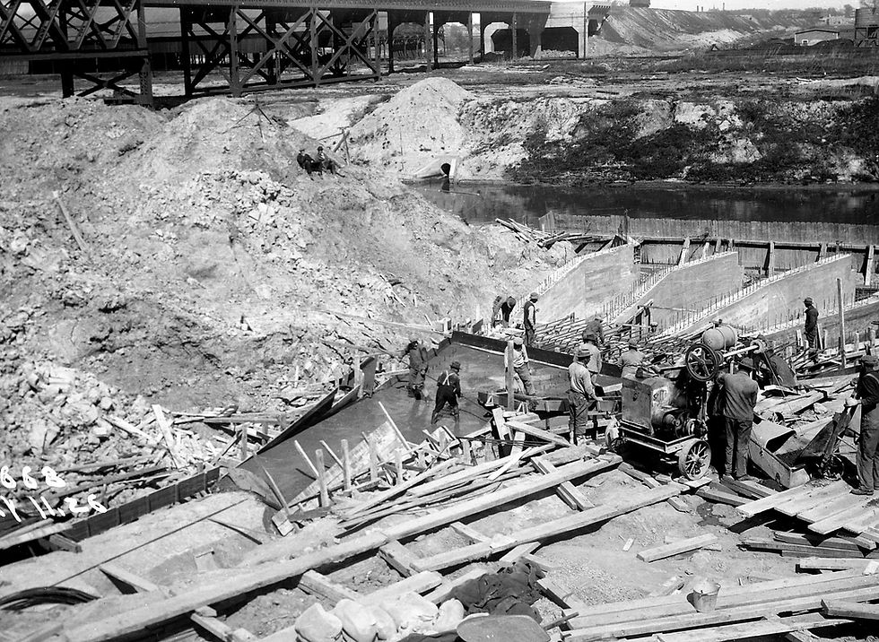
Looking northeast, May 11, 1926. Construction of the effluent outfall. The single effluent conduit diverges into five passages at the outfall to reduce the turbulence in the channel. The effluent flows south to the North Branch, but because of temperature and chemical differences between the effluent and water in the channel when the upstream channel is stagnant, a temporal density current can impact the channel as far north as Main Street. (MWRD photo 12668)

The channel cofferdam remains in place in this July 9, 1926, view, but has been breached to allow water into the outfall and effluent conduit. This photograph, taken from the electric railroad bridge, also shows in the background construction of the pump and blower building at left of center and preliminary settling tanks to the right of center. (MWRD photo 12808)

July 30, 1928. The Service Building contains the central boiler plant and maintenance shops. The tower contains a 150,000-gallon water tank providing an adequate supply and consistent pressure for the entire plant. At the time this plant was built, water was obtained through a dedicated water main from a City valve vault at Kedzie and Touhy avenues. The chimney, an imposing landmark for several years, was reduced in height in 1992. The building also houses a storeroom. (MWRD photo 14199)

July 30, 1928. The electrical substation in a separate building was outfitted to use electricity from the Lockport Powerhouse via the transmission line to Wilmette and also from Public Service Company of Northern Illinois transmission lines. Power from Lockport was phased out with the reduction in Lake Michigan diversion after 1930. (MWRD photo 14204)

April 15, 2015. The disinfection facility, under construction and due to be placed in service in 2016. The disinfection process was added to meet a new effluent limit for fecal coliform bacteria. The process uses ultraviolet (UV) radiation to inactivate both good and bad bacteria and other pathogens in the final effluent. In the building at right, high intensity bulbs emit UV light as final effluent passes around the bulb. (Photo by author)